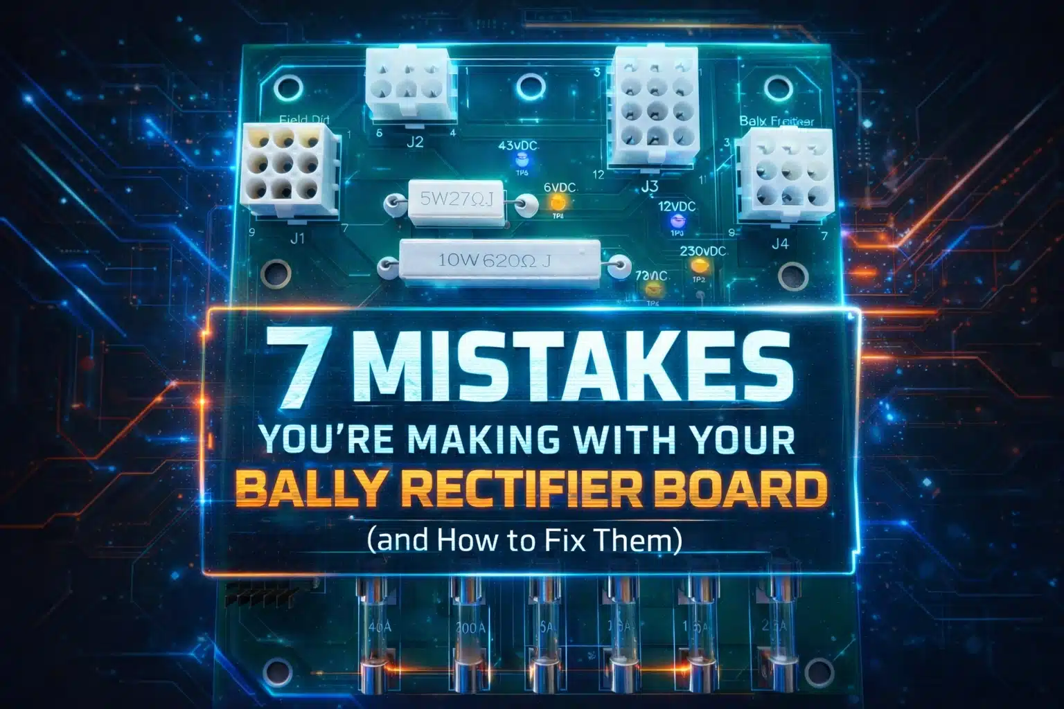
So, you have a classic Bally pinball machine sitting in the corner, and it is acting like a moody teenager. One minute it is playing fine, the next the displays are flickering, or worse, the whole thing just goes dark. Most of the time, the culprit is the heart of the power system: the Bally Rectifier Board, specifically that legendary AS-2518-54.
At GeekPCB's, we live for the smell of solder in the morning. We know that these machines were built to last, but even the best engineering from the late seventies and early eighties has an expiration date. If your board is original, it has been cooking in its own juices for over forty years. Mistakes happen when you are trying to keep these beasts alive, and that is just part of the DIY journey. But why make things harder than they need to be?
Let’s dive into the seven most common mistakes we see people making with their Bally rectifier boards and how you can fix them like a pro.
1. The Frankenstein Approach: Reusing Ancient Parts
We get it. You want to keep it original. You have a drawer full of old components that look "mostly fine." But here is the truth: reusing forty year old bridge rectifiers or capacitors is like trying to run a marathon in shoes held together by duct tape. It might work for a mile, but you are going to feel the pain eventually.
Many hobbyists try to "patch" their AS-2518-54 by swapping out a single blown fuse holder or a leaky cap with another used part. This creates a mismatch in performance and reliability. The fix? Always use new, high quality components. If you are doing a rebuild, replace the whole set of bridge rectifiers and capacitors at once. Or, even better, skip the headache and grab a premium reproduction board from our shop.

2. Wiring Spaghetti and Short Cuts
When you are looking at the back of a rectifier board, the wiring can look like a nightmare of colorful noodles. A common mistake is cutting the wires too short during a swap or failing to document where they go. We have seen people cut wires right at the solder point, losing the color coding and leaving themselves with a puzzle that even a master cryptographer couldn't solve.
The fix? Take your time. Cut about a half inch of wire but leave enough of the insulation so the color is still visible. Use your phone to take twenty photos from different angles before you touch anything. When you install a new board, connect the wires one by one. It is slow, it is tedious, but it is how you avoid blowing up your machine.
3. Ignoring the "Toastiness" of Your Connectors
If your connector pins look like they have been through a small house fire, they probably have. Heat damage is the silent killer of pinball electronics. Poor connections create resistance, resistance creates heat, and heat turns your plastic housings into brittle, charred remains.
Simply plugging a shiny new rectifier board into a burnt connector is a recipe for disaster. The old, warped connector won't make a solid contact, and you will be right back where you started in a month. The fix? Replace the connectors entirely. Use high quality crimp pins and new housings. It is a bit of extra work, but it ensures a solid, reliable connection for the next few decades.

4. The "Shaky Hands" Solder Joint
Cold or cracked solder joints are responsible for more "ghost" issues than actual haunted houses. Because the rectifier board is mounted to the transformer assembly, it deals with constant vibration and thermal expansion. Over time, the solder around the fuse clips and headers can crack.
You might think a quick dab of solder is enough, but if you don't clean the old oxidation off first, you are just layering fresh solder on top of a problem. The fix? Desolder the old joint completely and apply fresh, high quality solder. If the board traces are lifting or damaged, it is time to retire the old girl. Our reproduction boards at GeekPCB's feature heavy duty traces and superior solder masks to prevent these issues from happening in the first place. You can find more tech heavy solutions in our tech DIY boards section.
5. Playing Voltage Roulette
We have seen it happen: someone finishes a repair, flips the switch, and pop. They accidentally swapped a high voltage line with a low voltage one because they didn't check the test points. The AS-2518-54 has specific test points for a reason.
The fix? Never, ever flip that power switch without checking your work. Use a digital multimeter to verify the voltages at the designated test points on the board. Check your 5V, 12V, and the high voltage lines for the displays. If the numbers look weird, stop immediately and retrace your steps.
6. Neglecting the Heat Sink Grease
The bridge rectifiers on these boards get hot. Really hot. They rely on being mounted to a metal plate to dissipate that heat. A major mistake people make is either forgetting to use heat sink grease or using so much of it that it becomes a gooey mess that traps heat instead of moving it.
The fix? Apply a thin, even layer of thermal grease between the bridge rectifier and the mounting plate. Position the board carefully to avoid smearing it everywhere. Ensure the mounting screws are tight but not stripped. Proper heat management is the difference between a board that lasts five years and one that lasts fifty.
7. Using "Temporary" Fixes Permanently
We have all been there. You just want to play one game, so you use a bit of electrical tape to hold a wire in place or bypass a fuse with a piece of foil (please don't do this). The problem is that "temporary" often becomes permanent until something smells like burning ozone.
The fix? Do it right the first time. Use the proper screwdriver tightened connectors or high quality crimps. Avoid tape like the plague. It dries out, leaves a sticky residue, and doesn't provide a secure electrical connection. If you are working on a restoration, treat the machine with the respect it deserves.
Why a GeekPCB's Reproduction Board is the Ultimate Fix
Look, we love a good repair job as much as the next geek, but sometimes the original board is just too far gone. Decades of "hacks" and heat damage can leave the fiberglass weak and the traces peeling.
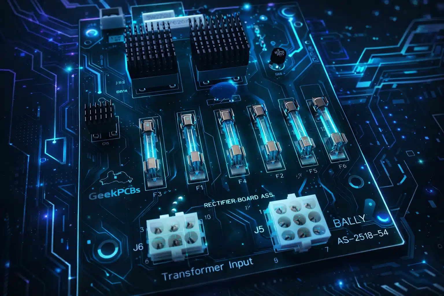
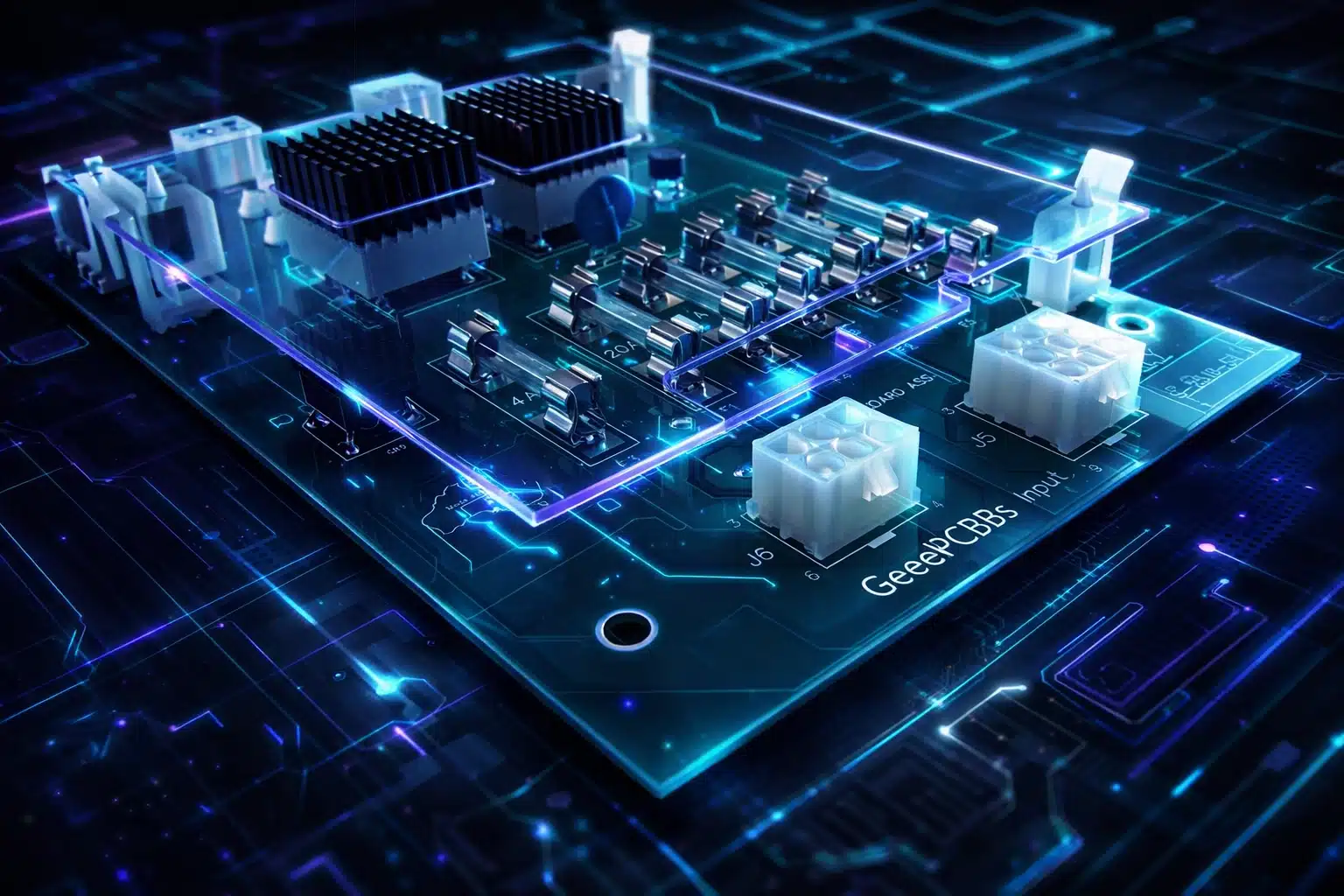
Our premium reproduction AS-2518-54 boards are designed for hobbiest who want a seamless, plug and play experience. We have upgraded the original design with:
- Thicker copper traces for better current handling.
- High quality components that exceed original specs.
- Clear labeling to make installation a breeze.
- Reliable fuse clips that won't lose their tension.
Whether you are fixing up a Bally classic or a Stern equivalent like the AS-2518-18, having a solid power foundation is non negotiable. Because they look sexy and why not? Plus, it gives you the peace of mind to actually enjoy playing your machine rather than constantly worrying about the next failure.
Ready to Build Something Awesome?
Don't let a dodgy rectifier board keep your machine in the dark. Mistakes are just learning opportunities in disguise, but now that you know the pitfalls, you can avoid them. If you are ready to give your machine the power it deserves, check out our full range of pinball and arcade parts.
Enjoy the read? It is riveting information, we know. But more importantly, it is the key to keeping these pieces of history alive for the next generation of gamers.
Frequently Asked Questions
Q: Can I use the AS-2518-54 in a Bally only machine? A: Yes, many Bally machines of that era are compatible. Always check your manual for specific product details to ensure a perfect match.
Q: Why are my fuses blowing even after I replaced the board? A: A new board provides clean power, but if there is a short elsewhere in the machine (like a stuck solenoid or a bad bridge rectifier in the head), the fuse will still blow to protect the circuit. Check your wiring down the line.
Q: Is it hard to install a new rectifier board? A: It requires some soldering skills and patience with wiring. If you are comfortable following a diagram and taking photos, it is a very satisfying DIY project. If you get stuck, we have a bunch of resources and a FAQ page to help you out.
Q: Why are there 2 x 15 Amp fuses for your GI lamps F5 and F6? A: This was a factory upgrade fitted to the last few Bally machines. It separates the headbox and lower cabinet general illumination circuits, giving each its own fuse. This makes it much easier to isolate and diagnose GI faults.
High quality, tested, and made for makers like you. That is the GeekPCB's promise. Now go get that machine running!